A network is any collection of independent computers that communicate with one another over a shared network medium. LANs are networks usually confined to a geographic area,
such as a single building or a college campus. LANs can be small,
linking as few as three computers, but often link hundreds of computers
used by thousands of people. The development of standard networking
protocols and media has resulted in worldwide proliferation of LANs
throughout business and educational organizations.
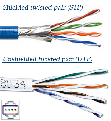
Is more common in high-speed networks. The biggest difference you
will see in the UTP and STP is that the STP use's metallic shield
wrapping to protect the wire from interference.
-Something else to note about these cables is that they are defined in
numbers also. The bigger the number the better the protection from
interference. Most networks should go with no less than a CAT 3 and CAT 5
is most recommended.
-Now you know about cables we need to know about connectors. This is
pretty important and you will most likely need the RJ-45 connector. This
is the cousin of the phone jack connector and looks real similar with
the exception that the RJ-45 is bigger. Most commonly your connector are
in two flavors and this is BNC (Bayonet Naur Connector) used in
thicknets and the RJ-45 used in smaller networks using UTP/STP.
Unshielded Twisted Pair (UTP)
This is the most popular form of cables in the network and the
cheapest form that you can go with. The UTP has four pairs of wires and
all inside plastic sheathing. The biggest reason that we call it Twisted
Pair is to protect the wires from interference from themselves. Each
wire is only protected with a thin plastic sheath.
Ethernet Cabling
Now to familiarize you with more on the Ethernet and it's cabling we
need to look at the 10's. 10Base2, is considered the thin Ethernet,
thinnet, and thinwire which uses light coaxial cable to create a 10 Mbps
network. The cable segments in this network can't be over 185 meters in
length. These cables connect with the BNC connector. Also as a note
these unused connection must have a terminator, which will be a 50-ohm
terminator.
10Base5, this is considered a thicknet and is used with
coaxial cable arrangement such as the BNC connector. The good side to
the coaxial cable is the high-speed transfer and cable segments can be
up to 500 meters between nodes/workstations. You will typically see the
same speed as the 10Base2 but larger cable lengths for more versatility.
10BaseT, the “T” stands for twisted as in UTP
(Unshielded Twisted Pair) and uses this for 10Mbps of transfer. The down
side to this is you can only have cable lengths of 100 meters between
nodes/workstations. The good side to this network is they are easy to
set up and cheap! This is why they are so common an ideal for small
offices or homes.
100BaseT, is considered Fast Ethernet uses STP
(Shielded Twisted Pair) reaching data transfer of 100Mbps. This system
is a little more expensive but still remains popular as the 10BaseT and
cheaper than most other type networks. This on of course would be the
cheap fast version.
10BaseF, this little guy has the advantage of fiber
optics and the F stands for just that. This arrangement is a little more
complicated and uses special connectors and NIC's along with hubs to
create its network. Pretty darn neat and not to cheap on the wallet.
An important part of designing and installing an Ethernet is selecting
the appropriate Ethernet medium. There are four major types of media in
use today: Thickwire for 10BASE5 networks, thin coax for 10BASE2
networks, unshielded twisted pair (UTP) for 10BASE-T networks and fiber
optic for 10BASE-FL or Fiber-Optic Inter-Repeater Link (FOIRL) networks.
This wide variety of media reflects the evolution of Ethernet and also
points to the technology's flexibility. Thickwire was one of the first
cabling systems used in Ethernet but was expensive and difficult to use.
This evolved to thin coax, which is easier to work with and less
expensive.
Network Topologies:
What is a Network topology?
A network topology is the geometric arrangement of nodes and cable links in a LAN,
There are three topology's to think about when you get into networks. These are the star, rind, and the bus.
Star, in a star topology each node has a dedicated set
of wires connecting it to a central network hub. Since all traffic
passes through the hub, the hub becomes a central point for isolating
network problems and gathering network statistics.
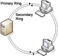
Ring, a ring topology features a logically closed loop.
Data packets travel in a single direction around the ring from one
network device to the next. Each network device acts as a repeater,
meaning it regenerates the signal
Bus, the bus topology, each node (computer, server,
peripheral etc.) attaches directly to a common cable. This topology most
often serves as the backbone for a network. In some instances, such as
in classrooms or labs, a bus will connect small workgroups
Collisions:
Ethernet is a shared media, so there are rules for sending packets of
data to avoid conflicts and protect data integrity. Nodes determine
when the network is available for sending packets. It is possible that
two nodes at different locations attempt to send data at the same time.
When both PCs are transferring a packet to the network at the same time,
a collision will result.
Minimizing collisions is a crucial element in the design and operation
of networks. Increased collisions are often the result of too many users
on the network, which results in a lot of contention for network
bandwidth. This can slow the performance of the network from the user's
point of view. Segmenting the network, where a network is divided into
different pieces joined together logically with a bridge or switch, is
one way of reducing an overcrowded network.
Ethernet Products:
The standards and technology that have just been discussed help
define the specific products that network managers use to build Ethernet
networks. The following text discusses the key products needed to build
an Ethernet LAN.
Transceivers
Transceivers are used to connect nodes to the
various Ethernet media. Most computers and network interface cards
contain a built-in 10BASE-T or 10BASE2 transceiver, allowing them to be
connected directly to Ethernet without requiring an external
transceiver. Many Ethernet devices provide an AUI connector to allow the
user to connect to any media type via an external transceiver. The AUI
connector consists of a 15-pin D-shell type connector, female on the
computer side, male on the transceiver side. Thickwire (10BASE5) cables
also use transceivers to allow connections.
For Fast Ethernet networks, a new interface called the MII (Media
Independent Interface) was developed to offer a flexible way to support
100 Mbps connections. The MII is a popular way to connect 100BASE-FX
links to copper-based Fast Ethernet devices.
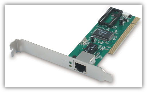
Network Interface Cards:
Ethernet switches are an expansion of the concept in
Ethernet bridging. LAN switches can link four, six, ten or more
networks together, and have two basic architectures: cut-through and
store-and-forward. In the past, cut-through switches were faster because
they examined the packet destination address only before forwarding it
on to its destination segment. A store-and-forward switch, on the other
hand, accepts and analyzes the entire packet before forwarding it to its
destination.
It takes more time to examine the entire packet, but it allows the
switch to catch certain packet errors and keep them from propagating
through the network. Both cut-through and store-and-forward switches
separate a network into collision domains, allowing network design rules
to be extended. Each of the segments attached to an Ethernet switch has
a full 10 Mbps of bandwidth shared by fewer users, which results in
better performance (as opposed to hubs that only allow bandwidth sharing
from a single Ethernet). Newer switches today offer high-speed links,
FDDI, Fast Ethernet or ATM. These are used to link switches together or
give added bandwidth to high-traffic servers. A network composed of a
number of switches linked together via uplinks is termed a "collapsed
backbone" network.
Routers:
Routers filter out network traffic by specific
protocol rather than by packet address. Routers also divide networks
logically instead of physically. An IP router can divide a network into
various subnets so that only traffic destined for particular IP
addresses can pass between segments. Network speed often decreases due
to this type of intelligent forwarding. Such filtering takes more time
than that exercised in a switch or bridge, which only looks at the
Ethernet address. However, in more complex networks, overall efficiency
is improved by using routers.
What is a network firewall?
A firewall is a system or group of systems that enforces an access
control policy between two networks. The actual means by which this is
accomplished varies widely, but in principle, the firewall can be
thought of as a pair of mechanisms: one which exists to block traffic,
and the other which exists to permit traffic. Some firewalls place a
greater emphasis on blocking traffic, while others emphasize permitting
traffic. Probably the most important thing to recognize about a firewall
is that it implements an access control policy. If you don't have a
good idea of what kind of access you want to allow or to deny, a
firewall really won't help you. It's also important to recognize that
the firewall's configuration, because it is a mechanism for enforcing
policy, imposes its policy on everything behind it. Administrators for
firewalls managing the connectivity for a large number of hosts
therefore have a heavy responsibility.
Network Design Criteria:
Ethernets and Fast Ethernets have design rules that must be followed
in order to function correctly. Maximum number of nodes, number of
repeaters and maximum segment distances are defined by the electrical
and mechanical design properties of each type of Ethernet and Fast
Ethernet media.
A network using repeaters, for instance, functions with the timing
constraints of Ethernet. Although electrical signals on the Ethernet
media travel near the speed of light, it still takes a finite time for
the signal to travel from one end of a large Ethernet to another. The
Ethernet standard assumes it will take roughly 50 microseconds for a
signal to reach its destination.
Ethernet is subject to the "5-4-3" rule of repeater placement: the
network can only have five segments connected; it can only use four
repeaters; and of the five segments, only three can have users attached
to them; the other two must be inter-repeater links.
If the design of the network violates these repeater and placement
rules, then timing guidelines will not be met and the sending station
will resend that packet. This can lead to lost packets and excessive
resent packets, which can slow network performance and create trouble
for applications. Fast Ethernet has modified repeater rules, since the
minimum packet size takes less time to transmit than regular Ethernet.
The length of the network links allows for a fewer number of repeaters.
In Fast Ethernet networks, there are two classes of repeaters. Class I
repeaters have a latency of 0.7 microseconds or less and are limited to
one repeater per network. Class II repeaters have a latency of 0.46
microseconds or less and are limited to two repeaters per network. The
following are the distance (diameter) characteristics for these types of
Fast Ethernet repeater combinations:
| Fast Ethernet |
Copper |
Fiber |
No Repeaters
One Class I Repeater
One Class II Repeater
Two Class II Repeaters |
100m
200m
200m
205m |
412m*
272m
272m
228m |
* Full Duplex Mode 2 km
When conditions require greater distances or an increase in the number
of nodes/repeaters, then a bridge, router or switch can be used to
connect multiple networks together. These devices join two or more
separate networks, allowing network design criteria to be restored.
Switches allow network designers to build large networks that function
well. The reduction in costs of bridges and switches reduces the impact
of repeater rules on network design.
Each network connected via one of these devices is referred to as a separate collision domain in the overall network.
Types of Servers:
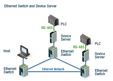
Device Servers
A device server is defined as a specialized,
network-based hardware device designed to perform a single or
specialized set of server functions. It is characterized by a minimal
operating architecture that requires no per seat network operating
system license, and client access that is independent of any operating
system or proprietary protocol. In addition the device server is a
"closed box," delivering extreme ease of installation, minimal
maintenance, and can be managed by the client remotely via a Web
browser.
Print servers, terminal servers, remote access servers and network time
servers are examples of device servers which are specialized for
particular functions. Each of these types of servers has unique
configuration attributes in hardware or software that help them to
perform best in their particular arena.
Print Servers
Print servers allow printers to be shared by other
users on the network. Supporting either parallel and/or serial
interfaces, a print server accepts print jobs from any person on the
network using supported protocols and manages those jobs on each
appropriate printer.
Print servers generally do not contain a large amount of memory;
printers simply store information in a queue. When the desired printer
becomes available, they allow the host to transmit the data to the
appropriate printer port on the server. The print server can then simply
queue and print each job in the order in which print requests are
received, regardless of protocol used or the size of the job.
Multiport Device Servers
Devices that are attached to a network through a multiport device
server can be shared between terminals and hosts at both the local site
and throughout the network. A single terminal may be connected to
several hosts at the same time (in multiple concurrent sessions), and
can switch between them. Multiport device servers are also used to
network devices that have only serial outputs. A connection between
serial ports on different servers is opened, allowing data to move
between the two devices.
Given its natural translation ability, a multi-protocol multiport device
server can perform conversions between the protocols it knows, like LAT
and TCP/IP. While server bandwidth is not adequate for large file
transfers, it can easily handle host-to-host inquiry/response
applications, electronic mailbox checking, etc. And it is far more
economical than the alternatives of acquiring expensive host software
and special-purpose converters. Multiport device and print servers give
their users greater flexibility in configuring and managing their
networks.
Whether it is moving printers and other peripherals from one network to
another, expanding the dimensions of interoperability or preparing for
growth, multiport device servers can fulfill your needs, all without
major rewiring.
Access Servers
While Ethernet is limited to a geographic area, remote users such as
traveling sales people need access to network-based resources. Remote
LAN access, or remote access, is a popular way to provide this
connectivity. Access servers use telephone services to link a user or
office with an office network. Dial-up remote access solutions such as
ISDN or asynchronous dial introduce more flexibility. Dial-up remote
access offers both the remote office and the remote user the economy and
flexibility of "pay as you go" telephone services. ISDN is a special
telephone service that offers three channels, two 64 Kbps "B" channels
for user data and a "D" channel for setting up the connection. With
ISDN, the B channels can be combined for double bandwidth or separated
for different applications or users. With asynchronous remote access,
regular telephone lines are combined with modems and remote access
servers to allow users and networks to dial anywhere in the world and
have data access. Remote access servers provide connection points for
both dial-in and dial-out applications on the network to which they are
attached. These hybrid devices route and filter protocols and offer
other services such as modem pooling and terminal/printer services. For
the remote PC user, one can connect from any available telephone jack
(RJ45), including those in a hotel rooms or on most airplanes.
Network Time Servers
A network time server is a server specialized in the handling of
timing information from sources such as satellites or radio broadcasts
and is capable of providing this timing data to its attached network.
Specialized protocols such as NTP or udp/time allow a time server to
communicate to other network nodes ensuring that activities that must be
coordinated according to their time of execution are synchronized
correctly. GPS satellites are one source of information that can allow
global installations to achieve constant timing.
IP Addressing:
An IP (Internet Protocol) address is a unique identifier for a node
or host connection on an IP network. An IP address is a 32 bit binary
number usually represented as 4 decimal values, each representing 8
bits, in the range 0 to 255 (known as octets) separated by decimal
points. This is known as "dotted decimal" notation.
Example: 140.179.220.200
It is sometimes useful to view the values in their binary form.
140 .179 .220 .200
10001100.10110011.11011100.11001000
Every IP address consists of two parts, one identifying the network and
one identifying the node. The Class of the address and the subnet mask
determine which part belongs to the network address and which part
belongs to the node address.
Address Classes:
There are 5 different address classes. You can determine which class
any IP address is in by examining the first 4 bits of the IP address.
Class A addresses begin with 0xxx, or 1 to 126 decimal.
Class B addresses begin with 10xx, or 128 to 191 decimal.
Class C addresses begin with 110x, or 192 to 223 decimal.
Class D addresses begin with 1110, or 224 to 239 decimal.
Class E addresses begin with 1111, or 240 to 254 decimal.
Addresses beginning with 01111111, or 127 decimal, are reserved for
loopback and for internal testing on a local machine. [You can test
this: you should always be able to ping 127.0.0.1, which points to
yourself] Class D addresses are reserved for multicasting. Class E
addresses are reserved for future use. They should not be used for host
addresses.
Now we can see how the Class determines, by default, which part of the
IP address belongs to the network (N) and which part belongs to the node
(n).
Class A -- NNNNNNNN.nnnnnnnn.nnnnnnn.nnnnnnn
Class B -- NNNNNNNN.NNNNNNNN.nnnnnnnn.nnnnnnnn
Class C -- NNNNNNNN.NNNNNNNN.NNNNNNNN.nnnnnnnn
In the example, 140.179.220.200 is a Class B address so by default the
Network part of the address (also known as the Network Address) is
defined by the first two octets (140.179.x.x) and the node part is
defined by the last 2 octets (x.x.220.200).
In order to specify the network address for a given IP address, the node
section is set to all "0"s. In our example, 140.179.0.0 specifies the
network address for 140.179.220.200. When the node section is set to all
"1"s, it specifies a broadcast that is sent to all hosts on the
network. 140.179.255.255 specifies the example broadcast address. Note
that this is true regardless of the length of the node section.
Private Subnets:
There are three IP network addresses reserved for private networks.
The addresses are 10.0.0.0/8, 172.16.0.0/12, and 192.168.0.0/16. They
can be used by anyone setting up internal IP networks, such as a lab or
home LAN behind a NAT or proxy server or a router. It is always safe to
use these because routers on the Internet will never forward packets
coming from these addresses
Subnetting an IP Network can be done for a variety of reasons, including
organization, use of different physical media (such as Ethernet, FDDI,
WAN, etc.), preservation of address space, and security. The most common
reason is to control network traffic. In an Ethernet network, all nodes
on a segment see all the packets transmitted by all the other nodes on
that segment. Performance can be adversely affected under heavy traffic
loads, due to collisions and the resulting retransmissions. A router is
used to connect IP networks to minimize the amount of traffic each
segment must receive.
Subnet Masking
Applying a subnet mask to an IP address allows you to identify the
network and node parts of the address. The network bits are represented
by the 1s in the mask, and the node bits are represented by the 0s.
Performing a bitwise logical AND operation between the IP address and
the subnet mask results in the Network Address or Number.
For example, using our test IP address and the default Class B subnet mask, we get:
10001100.10110011.11110000.11001000 140.179.240.200 Class B IP Address
11111111.11111111.00000000.00000000 255.255.000.000 Default Class B Subnet Mask
10001100.10110011.00000000.00000000 140.179.000.000 Network Address
Default subnet masks:
Class A - 255.0.0.0 - 11111111.00000000.00000000.00000000
Class B - 255.255.0.0 - 11111111.11111111.00000000.00000000
Class C - 255.255.255.0 - 11111111.11111111.11111111.00000000
CIDR -- Classless InterDomain Routing.
CIDR was invented several years ago to keep the internet from running
out of IP addresses. The "classful" system of allocating IP addresses
can be very wasteful; anyone who could reasonably show a need for more
that 254 host addresses was given a Class B address block of 65533 host
addresses. Even more wasteful were companies and organizations that were
allocated Class A address blocks, which contain over 16 Million host
addresses! Only a tiny percentage of the allocated Class A and Class B
address space has ever been actually assigned to a host computer on the
Internet.
People realized that addresses could be conserved if the class system
was eliminated. By accurately allocating only the amount of address
space that was actually needed, the address space crisis could be
avoided for many years. This was first proposed in 1992 as a scheme
called Supernetting.
The use of a CIDR notated address is the same as for a Classful address.
Classful addresses can easily be written in CIDR notation (Class A =
/8, Class B = /16, and Class C = /24)
It is currently almost impossible for an individual or company to be
allocated their own IP address blocks. You will simply be told to get
them from your ISP. The reason for this is the ever-growing size of the
internet routing table. Just 5 years ago, there were less than 5000
network routes in the entire Internet. Today, there are over 90,000.
Using CIDR, the biggest ISPs are allocated large chunks of address space
(usually with a subnet mask of /19 or even smaller); the ISP's
customers (often other, smaller ISPs) are then allocated networks from
the big ISP's pool. That way, all the big ISP's customers (and their
customers, and so on) are accessible via 1 network route on the
Internet.
It is expected that CIDR will keep the Internet happily in IP addresses
for the next few years at least. After that, IPv6, with 128 bit
addresses, will be needed. Under IPv6, even sloppy address allocation
would comfortably allow a billion unique IP addresses for every person
on earth
Examining your network with commands:
Ping
PING is used to check for a response from another computer on the
network. It can tell you a great deal of information about the status of
the network and the computers you are communicating with.
Ping returns different responses depending on the computer in question. The responses are similar depending on the options used.
Ping uses IP to request a response from the host. It does not use TCP
.It takes its name from a submarine sonar search - you send a short sound burst and listen for an echo - a ping - coming back.
In an IP network, `ping' sends a short data burst - a single packet -
and listens for a single packet in reply. Since this tests the most
basic function of an IP network (delivery of single packet), it's easy
to see how you can learn a lot from some `pings'.
To stop ping, type control-c. This terminates the program and prints out
a nice summary of the number of packets transmitted, the number
received, and the percentage of packets lost, plus the minimum, average,
and maximum round-trip times of the packets.
Sample ping session
PING localhost (127.0.0.1): 56 data bytes
64 bytes from 127.0.0.1: icmp_seq=0 ttl=255 time=2 ms
64 bytes from 127.0.0.1: icmp_seq=1 ttl=255 time=2 ms
64 bytes from 127.0.0.1: icmp_seq=2 ttl=255 time=2 ms
64 bytes from 127.0.0.1: icmp_seq=3 ttl=255 time=2 ms
64 bytes from 127.0.0.1: icmp_seq=4 ttl=255 time=2 ms
64 bytes from 127.0.0.1: icmp_seq=5 ttl=255 time=2 ms
64 bytes from 127.0.0.1: icmp_seq=6 ttl=255 time=2 ms
64 bytes from 127.0.0.1: icmp_seq=7 ttl=255 time=2 ms
64 bytes from 127.0.0.1: icmp_seq=8 ttl=255 time=2 ms
64 bytes from 127.0.0.1: icmp_seq=9 ttl=255 time=2 ms
localhost ping statistics
10 packets transmitted, 10 packets received, 0% packet loss
round-trip min/avg/max = 2/2/2 ms
meikro$
The Time To Live (TTL) field can be interesting. The
main purpose of this is so that a packet doesn't live forever on the
network and will eventually die when it is deemed "lost." But for us, it
provides additional information. We can use the TTL to determine
approximately how many router hops the packet has gone through. In this
case it's 255 minus N hops, where N is the TTL of the returning Echo
Replies. If the TTL field varies in successive pings, it could indicate
that the successive reply packets are going via different routes, which
isn't a great thing.
The time field is an indication of the round-trip time to get a packet
to the remote host. The reply is measured in milliseconds. In general,
it's best if round-trip times are under 200 milliseconds. The time it
takes a packet to reach its destination is called latency. If you see a
large variance in the round-trip times (which is called "jitter"), you
are going to see poor performance talking to the host
NSLOOKUP
NSLOOKUP is an application that facilitates looking
up hostnames on the network. It can reveal the IP address of a host or,
using the IP address, return the host name.
It is very important when troubleshooting problems on a network that you
can verify the components of the networking process. Nslookup allows
this by revealing details within the infrastructure.
NETSTAT
NETSTAT is used to look up the various active
connections within a computer. It is helpful to understand what
computers or networks you are connected to. This allows you to further
investigate problems. One host may be responding well but another may be
less responsive.
IPconfig
This is a Microsoft windows NT, 2000 command. It is very useful in determining what could be wrong with a network.
This command when used with the /all switch, reveal enormous amounts of troubleshooting information within the system.
Windows 2000 IP Configuration
Host Name . . . . . . . . . . . . : cowder
Primary DNS Suffix . . . . . . . :
Node Type . . . . . . . . . . . . : Broadcast
IP Routing Enabled. . . . . . . . : No
WINS Proxy Enabled. . . . . . . . : No
WINS Proxy Enabled. . . . . . . . : No
Connection-specific DNS Suffix . :
Description . . . . . . . . . . . :
WAN (PPP/SLIP) Interface
Physical Address. . . . . . . . . : 00-53-45-00-00-00
DHCP Enabled. . . . . . . . . . . : No
IP Address. . . . . . . . . . . . : 12.90.108.123
Subnet Mask . . . . . . . . . . . : 255.255.255.255
Default Gateway . . . . . . . . . : 12.90.108.125
DNS Servers . . . . . . . . . . . : 12.102.244.2
204.127.129.2
Traceroute
Traceroute on Unix and Linux (or tracert in the Microsoft world)
attempts to trace the current network path to a destination. Here is an
example of a traceroute run to
www.cumbuco-car-rental.com:
$ traceroute www.cumbuco-car-rental.com
traceroute to amber.www.cumbuco-car-rental.com (128.32.25.12), 30 hops max, 40 byte packets
1 sf1-e3.wired.net (206.221.193.1) 3.135 ms 3.021 ms 3.616 ms
2 sf0-e2s2.wired.net (205.227.206.33) 1.829 ms 3.886 ms 2.772 ms
3 paloalto-cr10.bbnplanet.net (131.119.26.105) 5.327 ms 4.597 ms 5.729 ms
4 paloalto-br1.bbnplanet.net (131.119.0.193) 4.842 ms 4.615 ms 3.425 ms
5 sl-sj-2.sprintlink.net (4.0.1.66) 7.488 ms 38.804 ms 7.708 ms
6 144.232.8.81 (144.232.8.81) 6.560 ms 6.631 ms 6.565 ms
7 144.232.4.97 (144.232.4.97) 7.638 ms 7.948 ms 8.129 ms
8 144.228.146.50 (144.228.146.50) 9.504 ms 12.684 ms 16.648 ms
9 f5-0.inr-666-eva.cumbuco-car-rental.com (198.128.16.21) 9.762 ms 10.611 ms 10.403 ms
10 f0-0.inr-107-eva.cumbuco-car-rental.com (128.32.2.1) 11.478 ms 10.868 ms 9.367 ms
11 f8-0.inr-100-eva.cumbuco-car-rental.com (128.32.235.100) 10.738 ms 11.693 ms 12.520 ms